
How to Test Continuity Using a Digital Multimeter (Step-by-Step Guide)
- Kalyan Bhattacharjee

- Dec 21, 2025
- 4 min read
Updated: May 4

Let's Dive In | Continuity Testing Using Multimeter
If you’ve ever dealt with a device that suddenly stopped working no power, no response, no obvious damage, chances are the problem wasn’t complicated at all. In many cases, it’s simply a broken wire, loose connection, or faulty component hiding in plain sight. This is where continuity testing using a digital multimeter (DMM) becomes one of the most valuable troubleshooting skills you can learn.
It’s simple, fast, and often the first test professionals perform before replacing parts or tearing down a circuit. Let’s walk through it properly, not just how to do it, but why it works and what most beginners get wrong.
What Is Continuity Testing?
Continuity testing checks whether electric current can flow uninterrupted between two points in a circuit.
In simple terms:
✔ Continuity present → Path is complete
✖ No continuity → Path is broken
A digital multimeter does this by sending a very small current through the circuit and checking if it returns. If it does, the meter confirms a complete path, often with a beep sound, which makes testing quick and intuitive.
When Should You Check Continuity?
Continuity testing is commonly used to:
Detect broken wires or cables
Test fuses and switches
Verify PCB traces
Check solder joints
Identify faulty connectors
Confirm ground connections
A lesser-known insight: Experienced technicians often check continuity before measuring voltage or resistance because there’s no point testing a circuit that isn’t even electrically connected.
What You Need
You only need two things:
A digital multimeter with continuity mode
The circuit, wire, or component you want to test
Most modern multimeters even budget ones, include continuity testing.
Understanding the Continuity Symbol on a Multimeter
Continuity mode is usually marked by:
A sound wave or diode symbol
Sometimes combined with the resistance (Ω) setting
When continuity is detected, the Multimeter
It produces a beep or visual indicator, confirming that the circuit path is complete and electrically connected. So, it:
Emits a beep
Displays a very low resistance value (usually close to 0Ω)
No beep usually means an open circuit, broken connection, or faulty component that prevents current from flowing.
Important Safety Rule (Don’t Skip This)
👉 Always power OFF the circuit before checking continuity.
Testing continuity on a live circuit can:
Damage the multimeter
Give false readings
In worst cases, harm the user
This is one of the most common beginner mistakes.
Step-by-Step: Check Continuity Using a Digital Multimeter
Follow these simple steps to safely test whether an electrical path is complete using a digital multimeter.
Turn Off Power
Disconnect the device from power. Remove batteries or unplug it from mains electricity. This prevents electric shock and protects both you and the multimeter from damage.
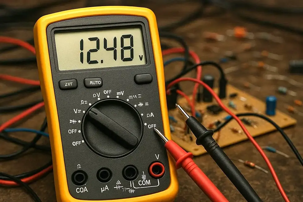
Set the Multimeter to Continuity Mode
Rotate the dial to the continuity symbol. Some meters require pressing a “mode” button. A beep or symbol on the display confirms that continuity mode is active.
Test the Multimeter
Touch the two probes together.
✔ You should hear a beep
✔ The display should show near-zero resistance
If not, check the meter’s battery or probe connections.
Place the Probes on Test Points
Touch one probe to each end of:
A wire
A fuse
A PCB trace
A switch terminal
Probe polarity doesn’t matter for continuity testing.
Interpret the Result
Beep + low resistance → Continuity present
No beep / OL reading → Open circuit
That’s it - the result is immediate.
How to Test Common Components Using Continuity
This section shows how continuity mode can quickly identify breaks or faults in everyday electrical components.
Wires and Cables
Touch probes to both ends of the wire. No beep means the wire is broken internally. A continuous beep indicates the wire is intact and current can flow freely through it.
Fuses
A good fuse beeps. A blown fuse shows no continuity.
This test is far more reliable than visual inspection.
Switches
Test with the switch ON and OFF:
ON → Beep
OFF → No beep
If behavior doesn’t match, the switch is faulty.
PCB Traces
Used heavily in electronics repair. A missing beep often reveals cracked or burnt traces invisible to the eye. Continuity testing helps confirm whether current can flow properly through the trace without removing components from the board.
Continuity vs Resistance — What’s the Difference?
Many people confuse the two.
Continuity mode: Fast yes/no check
Resistance mode (Ω): Measures exact resistance value
Continuity mode is optimized for speed and audible feedback, which is why technicians prefer it during diagnostics.
Common Mistakes to Avoid
Testing a powered circuit
Forgetting to test the multimeter first
Touching probes with fingers (can affect readings)
Assuming “no beep” always means failure (some components need resistance mode instead)
Testing components still connected to complex circuits (parallel paths can mislead results)
Pro tip: For accurate results, isolate the component whenever possible.
Why Continuity Testing Matters in Real Repairs
Instead of replacing parts blindly, you can pinpoint the exact failure point in minutes. Continuity testing saves:
Time
Money
Guesswork
In professional repair environments, this simple test prevents unnecessary board replacements worth thousands.

Final Thoughts
Learning how to check continuity using a digital multimeter is one of those foundational skills that pays off endlessly - whether you're fixing gadgets, working with PCBs, or just diagnosing household electronics.
It’s quick, safe (when done correctly), and incredibly powerful for troubleshooting. Once you get comfortable with it, you’ll wonder how you ever diagnosed problems without it.
Author: Kalyan Bhattacharjee
Category: Tech Tutorials | Hardware
Expertise: Computer Systems Analyst & Technology Research Writer
Source: Information compiled from electronics manuals, measurement standards, and publicly available technical guides
📚 Keep exploring - Here are more tech blogs you’ll love:
Related Keywords: continuity using multimeter, how to test continuity using a multimeter, how to measure continuity using a multimeter, how to use multimeter to test continuity, how to continuity test using multimeter, how to continuity test using multimeter, how to check continuity using multimeter, multimeter continuity test, continuity setting on multimeter, check continuity with multimeter, continuity electric, continuity test symbol, multimeter continuity beep meaning, continuity test for wires, continuity test for PCB, fintech shield

Comments